
Unpacking the Mechanical Core of Gas Power Generation
When project teams evaluate backup power systems, discussions often focus simply on fuel consumption and nameplate output ratings. However, a gas electric generator does much more than just burn fuel to create electricity. It moves energy through a precisely choreographed sequence of physical transformations: gaseous fuel releases thermal energy inside combustion chambers, the heavy engine converts that intense heat into smooth shaft rotation, and a high-performance alternator translates that mechanical energy into usable electrical output. Understanding this step-by-step energy conversion chain makes it vastly easier to select reliable equipment, evaluate generator sets, or troubleshoot voltage stability issues under complex industrial loads.
From an experienced engineer's perspective, the most critical question is not merely whether a gas generator can start up. It is whether the fuel supply, engine dynamics, alternator characteristics, control panels, site load profiles, and long-term maintenance protocols operate as a unified system. Because an electrical machine cannot create energy out of nothing, its output relies entirely on transforming the mechanical power delivered through the rotating engine crankshaft.
Tracing the Energy Path From Fuel to Shaft Rotation
Most industrial and commercial gas-fuelled generator sets follow a uniform internal energy path. First, chemical energy arrives in the form of natural gas, LPG, biogas, or another approved gaseous fuel entering the engine system. Second, combustion rapidly raises gas pressure and temperature inside the engine cylinders. Third, expanding combustion gases push heavy pistons downward, which rotates the crankshaft and primary drive shaft, generating mechanical energy. Fourth, the spinning shaft drives the alternator rotor to produce voltage across stationary stator windings. Finally, regulation, protection, switching, and distribution hardware deliver safe electricity to the connected facility loads.
Every single stage in this sequence incurs energy losses. Thermal energy escapes through exhaust systems and engine cooling jackets; friction consumes a fraction of shaft power; and copper resistance losses occur inside the alternator windings. This thermodynamic reality explains why electrical output is always lower than the raw chemical energy entering a gas generator.
How Combustion Produces Engine Torque and Speed
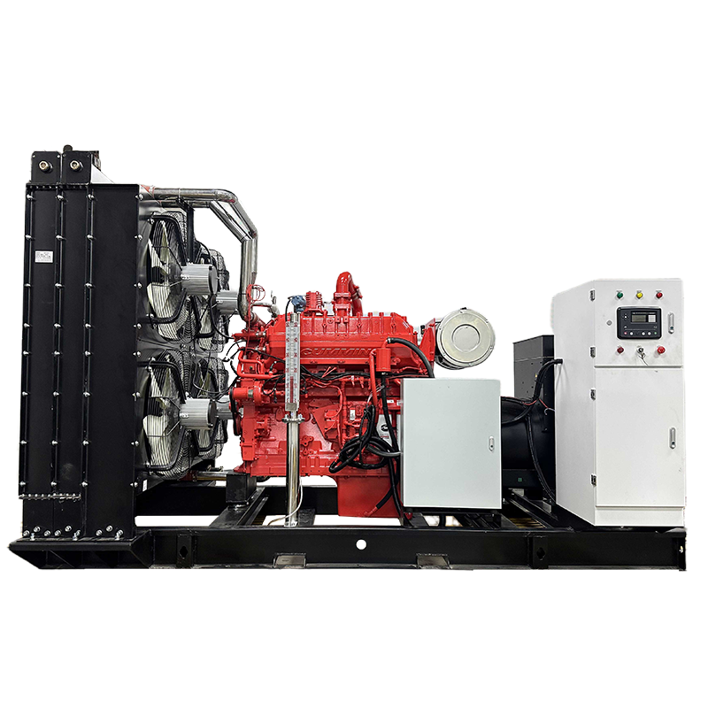
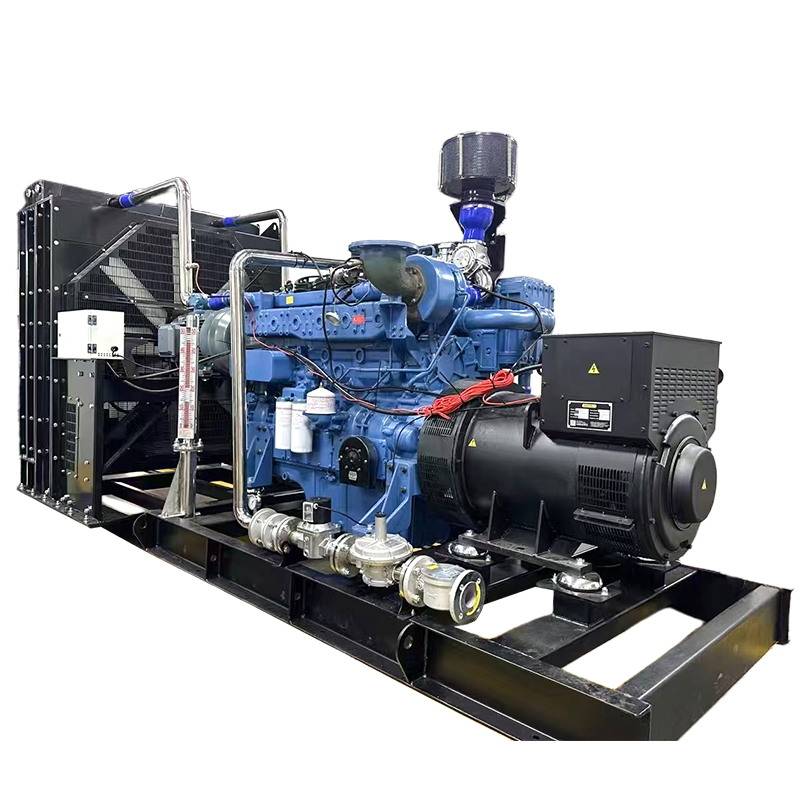
The engine acts as the primary prime mover in any gas generator setup. It blends gaseous fuel with incoming combustion air, compresses the mixture precisely, and ignites it at the exact optimal point in the cycle. The resulting combustion event creates high-pressure gases that force pistons downward with tremendous force. Connecting rods then transfer that linear motion to the crankshaft, translating repeated piston strokes into continuous rotation.
This rotation represents pure mechanical energy. Torque describes the twisting force available at the crankshaft, while rotational speed determines how quickly the shaft spins. Both parameters are vital. A gas generator must maintain adequate torque to carry heavy electrical loads while holding a strictly controlled rotational speed to preserve the exact alternating-current frequency required by sensitive electrical systems.
It is easy to focus exclusively on engine ratings, but the engine, electronic governor, fuel train, and load response mechanisms must function seamlessly together. If fuel pressure drops, air supply fluctuates, or governor response lags, the engine may fail to hold stable speed when facility loads shift rapidly.
Transforming Rotation Into Electricity via the Alternator
The rotating engine crankshaft couples directly to the alternator. Inside this electrical machine, the rotor serves as the moving magnetic-field component. A dedicated field winding receives excitation current to establish a powerful magnetic field. When the engine spins the rotor at high speeds, this magnetic field sweeps continuously past the stationary stator windings.
This interaction marks the pivotal conversion point in a gas electric generator. Motion is not pushed directly into a wire as electrical current; instead, the changing magnetic field relative to the stationary conductors induces voltage through electromagnetic induction. When an external electrical circuit connects to the system, current flows smoothly and power becomes accessible to facility equipment.
Shaft speed and magnetic field conditions dictate the generated voltage and frequency. For standard alternating-current systems, engineers select the alternator pole count and rotational speed to match target grid frequencies. Control systems then keep output stable as loads connect or disconnect.
The Stator and the Role of Voltage and Frequency Regulation
The stator houses the stationary output windings. As the rotating magnetic field sweeps across these coils, it induces alternating voltage. In standard three-phase industrial alternators, the stator is engineered to generate three distinct AC waveforms offset from one another, supporting balanced three-phase loads and highly efficient power distribution.
While the alternator changes mechanical input into electrical output, it does not dictate how much power a site consumes—the connected load does. When facility equipment demands higher current, the alternator experiences increased electromagnetic drag, resisting rotation more strongly. The engine must immediately respond by delivering greater torque and burning more fuel to maintain stable speed. This interdependent relationship explains why sudden load acceptance remains a central operational challenge for any gas generator.
To maintain stability, two automated control functions work continuously behind the scenes:
-
Speed Governing: The electronic governor adjusts fuel delivery instantly to help the engine maintain target speed despite sudden load fluctuations, safeguarding AC frequency stability.
-
Voltage Regulation: An automatic voltage regulator, or AVR, adjusts alternator excitation to stabilize output voltage as reactive and resistive loads vary across the facility.
Even advanced controls have operational limits. Large motor starts or sudden load steps can cause brief frequency dips. Such occurrences do not automatically mean the gas electric generator is defective; rather, they highlight the importance of matching generator ratings and fuel systems to the exact site load profile.
Engineering Excellence with Keya Power Solutions
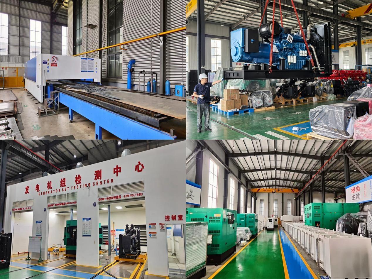
Designing resilient, high-performance power systems requires rigorous engineering, precise component selection, and advanced manufacturing capabilities. Keya delivers industry-leading renewable and intelligent power solutions tailored to demanding industrial and municipal applications. Through strict quality control, expert manufacturing, and dependable supply chain support, Keya helps global project teams engineer custom gas power systems that bridge local environmental standards with exceptional operational reliability.
 Hot News